
-
-
Remove Palette's top lid.
-
Using the provided Torx screwdriver, remove the 4 screws on each corner of the substructure.
-
Remove the IO plate cover from the unit, by pulling the tab on the Ethernet port. The IO plate cover is snap-fit to the unit and can be placed back easily.
-
Gently lift and remove the substructure from the bottom casing.
-
You'll now be able to replace the main board, fans, and other components.
-
-
-
Remove 6 screws on the main board to release it
-
Remove the blue ribbon cable between the main board and the ingoing drive board. Lift the black tab on both sides to release the cable, and gently pull the cable away from one end.
-
-
-
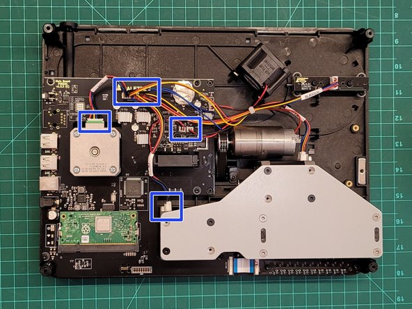
Remove the wires from the following ingoing/outgoing motors and two fans.
-
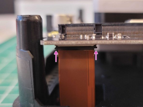
Remove screen ribbon cable by lifting the main board slightly, and then pull down on the black tab on the cable connection. This will release the screen cable, which can then be pulled away from the main board.
-
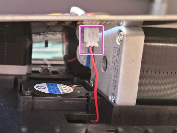
Remove screen fan connection from underneath main board
-
-
-
Remove the Pi from the old main board by lifting it out of the casing
-
Open the two metal fasteners on each side of the Pi to lift it out of the casing
-
Place the Pi into the new main board, and click it into place using the two metal fasteners on each side
-
-
-
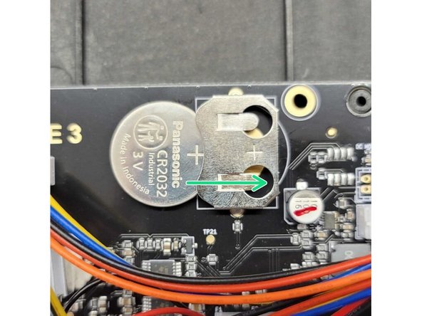
Remove the battery from the old main board, and insert into new main board. Insert the battery so that the (+) is on the right, and matches the position of the (+) symbol in its slot.
-
-
-
Place the new main board back in place.
-
Reconnect the screen ribbon cable and screen fan from underneath the main board.
-
Reconnect the blue ribbon cable between the main board and ingoing drive board.
-
-
-
Reconnect any disconnected cables between the main board and fans/motors.
-
Secure the main board back into place by returning the screws into these positions.
-
Complete the re-assembly by returning the substructure into the back casing, and screwing the four mounting screws back in place. Place the IO board cover back in place.
-


Cancel: I did not complete this guide.
One other person completed this guide.
